Reasoning the use of a rule based system.
As proviously discussed, the system modules of the analyse are based on the idea of having the possibility to use different contexts, each of them defining the rules, constrains and names of the flight procedures and situations.
These definitions are supposed to be as close approached as possible to what happen in the reality. This means that the overall quality of situation recognition and prediction depends on the quality of the defined context loaded at the time by the user in the memory of the Flight Gear Client.The advantage of the system that function with contexts is the possibility to avoid to make modifications in the project sources every time other set of rules are wanted. One great advantage would also be the fact that the user can load an already made context and can make any modifications as desired. It’s so possible to delete some situations, steps or directions, or to add such items or to modify any logical expression that is related to a certain step or direction. The Context Modeler program can automatically generate context diagrams for the user to help him to have a better outllook of what he is doing.
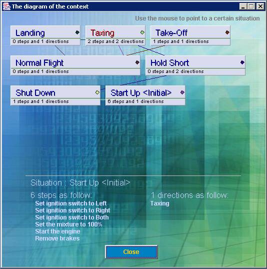
The diagram above show an example of what the Context Modeler program generates through the its Diagram Module. The image show the diagram of an already developed context with a full description of all flight situations and for each situation the set of steps and directions. The diagram builder module shows all the situations with the certain lines between the situations to asses the links that exists and that are based on the directions to follow being in that situation. When the user move the mouse over a rectangle that corresponds to a situation, for instance “Taxing”, the information realted to that situation is showed on the lower part of the diagram. It can be seen that in the diagram above. The sign <Initial> states for the initial situation, that is loaded the first time the Flight Gear Client loads the context file from the disk. Moreover, all the situations which are directions-targets to pointed one, are coloured in red to notice the fact. In the above one the mouse was over the “Start_Up” situation rectangle. Every situation has a rectangle and in the left side of it a filled circle is drawn. The filling colour indicates the colour of that situation on the diagram and every other situation that are directions-targets for the current, is linked to the current one by a line having the current situation colour. In this way it can be seen easily what directions are defined for a certain situation, not by moving the mouse over its rectangle.